Clonk has supported parallax objects and backgrounds for a while. Parallax scrolling is a method to create a faux 3d effect with only 2d methods by making objects move slower or faster when the imaginary camera moves across the landscape. This approach generally works well, but the effect this had when the zoom level changed was unfortunate. Instead of simply making parallax objects and backgrounds look the same way as the other objects when zoomed, Clonk-Karl and I figured out how they would behave if they really were before or behind the landscape. The first question we had to answer what different zoom levels represented in that virtual world: Does the distance between camera and landscape change, or do the camera optics, like a zoom lens? We eventually came to the conclusion that we needed both: the zoom lens to ensure that every player sees about the same picture independent of the pixel count of their monitor, and the distance change to represent zoom. While real-world zoom uses a zoom lens, real world unmodified humans do not, so changing the virtual distance should feel more natural.
Figuring out how the objects should display on a diagram was straightforward after that. Put a point for the camera, one line for the landscape and screen (the landscape always is on the same plane as the screen, because the screen is what keeps the sky islands from falling down), and one line for the object, and then draw lines from the edges of the object to the camera. The object should be displayed were those lines cross the screen. But we needed several iterations translating that to the formulas used in the engine because we hadn’t fully internalized what the given values meant. The position of the object is not where the object is in the virtual world, but where it is displayed on the landscape when the camera is at position 0/0, and the zoom factor is 1. And the camera is at position 0/0 when the upper left corner of the screen is there. It’s as if only the lower right quarter of the camera’s view is displayed. The reason is that the parallax math works out rather nice this way: When translating from landscape to screen coordinates, the position of the upper left corner of the screen is simply multiplied by the parallax factor and subtracted from the object’s position. But our first diagrams had the camera positions in the middle of the screen, which was confusing because it introduces the screen size into the formulas, which we knew is not there in the engine code.
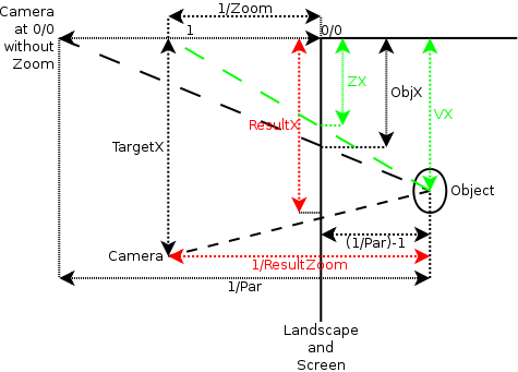
We finally arrived at what we believed were the correct formulas and put them into the engine. The result was for the most part satisfactory, especially the sky behaved nicely. But objects moved around on the screen when changing the zoom factor while moving as expected when just moving around. I finally discovered why when constructing this diagram a few days later:

The diagram shows a view from the side on the camera, landscape and one object. Because the formulas for X and Y are independent and identical, only one dimension is shown.
The black distances are given, the red distances are the ones we want to calculate. The green ones are intermediate results. The dashed lines are the lines of sight between camera and object.
At the top left of the diagram is the camera that defines the internal object positions: The position of an object is where this camera would see the object in the landscape. A bit to the right is a camera at position 0/0, but with a different zoom factor (called “Zoom”). Our first version mixed this camera up with the first one. This doesn’t matter for objects at position 0/0, which explains why the sky worked correctly: We only tested in a scenario where the sky doesn’t move with the wind.
Down from the second camera is the third one, the one for which the calculations are to be done. It has a distance of “TargetX” from the origin, and a zoom factor of “Zoom” like the second camera.
At the right there’s the object to be displayed. This one is behind the landscape, but fortunately the formulas work just as well for an object before the landscape. It’s distance on the Z axis from the first camera is “1/Par”, where “Par” is the parallax factor. Consequently, the distance to the landscape is “1/Par-1”, because the first camera has a distance of “1” from the landscape. The position in the virtual world on the X axis is “VX”.
Once I had this diagram, calculating the result is a simple application of the Intercept_theorem.Those interested in the result can take a look at the C4Object::GetDrawPosition() function in the engine.

 It’s been 9 months since the last full release. Time for another one! The most visible changes since 1.2 are: